What are the safety risks associated with electric roads?
Electric roads transmit high powers of up to 100’s of kilowatts from the road to the vehicles. For that reason there are a number of safety regulations and precautions in place to ensure that no electrical accidents occur, making the safety risks minimal.
Electric roads can be compared with the overhead contact lines used for trams and trolley buses. Here the contact lines are suspended in air above the streets in the city centers, with a life threatening voltage and without isolation. However, there is virtually never an accident related to this transmission technology. For more than 100 years we have gotten accustomed to the fact that it actually works safely. Today, as the next generation of electric roads are installed on our roads, we need to relate to modern electric roads in the same way.
The risks and precautions
These are the risks, that after all exist, and the safety precautions that are in place. Different technologies come with different risks and precautions. The risks can be divided into:
- Electrical risks: the road
- Electrical risks: the vehicle
- Mechanical risks: the road
- Thermal risks: the road
- Magnetic risks: the road
Electrical risks: the road
An exposed and powered uninsulated contact rail is fatal to touch. For that reason, there are a number of safety precautions in place to ensure that no electrical accident occurs. The different technologies use different solutions:
Contact lines in the air have a built-in safety because they are difficult to reach, suspended 5-6 meters above ground. Should a contact line fall down, there are measurement systems that detect this and immediately switch off the voltage to the line.
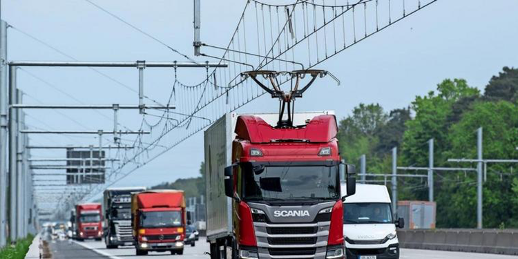
Example: Siemens eHighway
Contact rails on the ground surface are divided into sections and the voltage is activated only when vehicles with proper equipment use the road.
Examples: Elonroad, Alstom and Honda
In cases where the contact rails are longer than the vehicle, as in Alstom’s and Honda’s solution, they are only activated above a certain speed, since no one is expected to stand right in front or step in just behind a moving vehicle.
In the case where the contact rails are shorter than the vehicle, as in Elonroad’s solution, the rails can be activated even when the vehicle is stationary because the vehicle then covers the rails. In that case, there are also several independent systems that detect if anything (a ball, a cat or a hand) reaches beneath the vehicle. Should this occur, the voltage is immediately switched off.
The contact rails below ground surface are also divided into relatively long sections, that are activated when vehicles pass, but because they are submerged in narrow tracks in the road surface, they are difficult to reach. The top of these tracks is also a grounded metal rail which further increases safety.
Example: Elways
Electrical risks: the vehicle
Electrical appliances generally solve electrical safety in one of two ways:
Protective earthing
The device has an electrical grounded case, a so-called protective earthing. This means that all accessible parts, such as the outside of a toaster or stove is connected to electrical grounding and a ground fault circuit breaker detects electrical faults. Should an electrical fault occur, the power is turned off. Electric grounding means that the electrical voltage is close to zero volts, which is harmless to get in contact with.
Double Insulation
The device lacks connection to protective ground but is instead doubly insulated. This means that all electrical circuits in the device are insulated in a ”subframe”. This ”subframe”. is in turn electrically insulated the outer frame or casing that the user can hold on to. Two layers of insulation thus, hence the term “double insulated”. Two simultaneous insulation faults are required for the outer casing to be powered with a dangerous voltage. This is considered so unlikely to occur that it is a widely accepted security solution.
Conductive electric roads are doubly insulated
With conductive electric roads, the challenge is that you cannot guarantee that the vehicle is always connected to protective earth. This is because you cannot know for sure if, for example, a leaf, a piece of paper or a plastic bag has come between a grounded rail and a sliding contact for protective ground connection of the vehicle chassis. Therefore, a security solution based on protective earthing is not conceivable.
Thus, double insulation remains. The solution for electrical safety on board conductively connected electric road vehicles is therefore to ensure that the electrical circuits on board the vehicle connected to the rails of the electric road are mounted in an insulated subframe. This internal subframe is in turn isolated from the vehicle’s outer frame or chassis, i.e. what you can get in contact with. That means there are two levels of insulation, in other words double insulation, the same as in a hair dryer. This solution is used, among other things, in trolley buses.
In case of insulation failure, the power is immediately turned off
In addition to the double insulation itself, there are also systems for measuring the degree of insulation between the ”subframe” mentioned above and the vehicle’s outer chassis (which can be touched). Should the insulation between the subframe and the touchable chassis indicate a too low value, either the car is either recommended for service or the electrical connection will be cut off, depending on the degree of insulation failure detected.
Mechanical risks: the road
These risks are associated with the impact on the road surface or the surroundings of the road caused by the electric road technology. They can be divided into four groups:
1. Obstacles on the side of the road. All electrical road technologies need to be powered, which means that there must be a transformer and rectifier station at the side of the road at regular intervals (a few tens of meters up to a few hundreds of meters). These can be dug down but if standing on the ground they become an obstacle close to the side of the road.
In addition, with contact lines in the air (as in the example Siemens eHighway), poles are needed at regular intervals that support the contact lines at a height of 5-6 meters. These poles are also physical obstacles close to the side of the road.
2. Rail on top of the ground (one of Elonroad’s variants) forms a low (3-5 cm) road bump in the middle of the lane. It is not perceived as an obstacle when you shift lanes with a passenger car, but it might be with a motorcycle. For this reason, this solution will probably not be used on country roads but only in urban environments.
3. Rail at the same level as the ground (another of Elonroad’s variants, as well as Alstom’s). Since the contact rail is made of metal, the friction is lower than the surrounding asphalt, just like the friction is lower when the white lines in the road are all wet. This is to some extent compensated by the rails being provided with an engraved pattern that improves the friction for the rubber tires of the vehicles.
4. Electric road rails immersed in the ground. Here only the tracks in which the rails are submerged can be seen as a mechanical risk. The tracks are narrow (<2cm) and it is really only racing bikes with really narrow tires that would perceive it as unsafe.
If a contact rail or contact line in any way is damaged or torn up/down, it is immediately detected by various safety systems and the voltage to the road is switched off.
These mechanical risks don’t apply to inductive electric roads.
Thermal risks: the road
With all conductive electric roads there is a so-called “contact resistance” between the contact line (Siemens eHighway) or the contact rail (all others) and the sliding contact receiving the power. In this contact resistance, heat develops as the current passes, typically up to about 100 Watts when transmitting 100-200 kilowatts. As long as the vehicle is in motion, this heat is spread along the line/rail and results in a low temperature rise, causing no harm.
However, if the vehicle is stationary when it is charging, the contact point and its close surroundings will heat up, and may become rather warm, up to 70-90 degrees Celsius. If the vehicle finishes charging and immediately leaves, then it leaves behind a hot contact point that takes a few minutes to cool off, without any active cooling. This is a problem for the technologies where the contact rail is unprotected, but there are also solutions.
There are three main ways to limit the rise in temperature:
- The contact point is cooled by an air flow from the vehicle. A fan simply directs the cabin air (which is usually air-conditioned) to the contact point.
- The contact point temperature is measured during charging and the charging current is limited so that the temperature does not reach higher, potentially harmful temperatures.
- The vehicle is not allowed to leave the charging station until the cooling air flow has ensured a sufficiently low temperature. It’s usually a matter of seconds.
Magnetic risks: the road
An inductive charger for electric vehicles is designed much like an induction stove. In the ground there is an electrical coil in which a high frequency current (normally 85 kHz) is driven which forms a high frequency magnetic field which is picked up by a corresponding electric coil under the vehicle. In an induction stove, it is the saucepan itself which is the receiver and the currents formed by the magnetic field in the saucepan bottom generate heat. Instead, in the vehicle charger, the currents generated in the coil beneath the vehicle are passed to the vehicle battery that is charged.
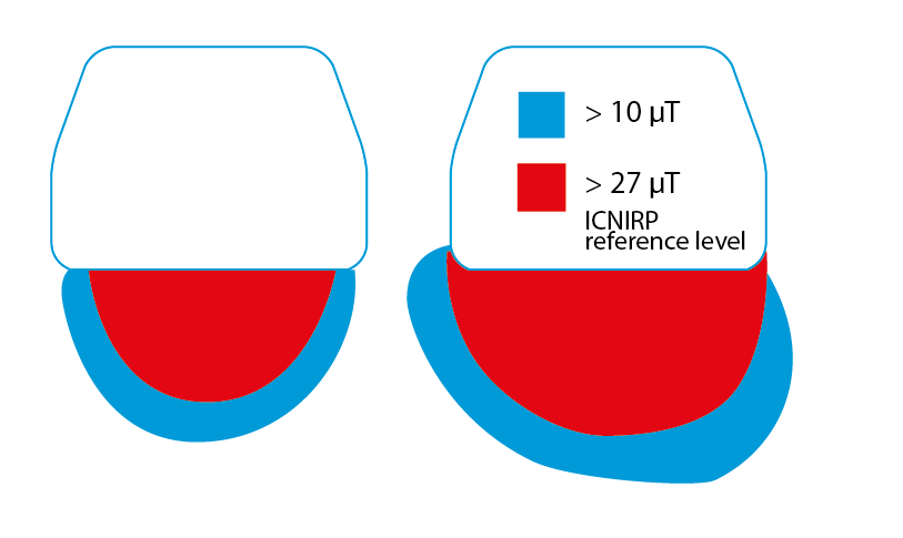
The magnetic field that transfers the energy from the coil on the ground to the coil under the car “leaks” a little towards the sides of the car. The leak increases if the car isn’t parked so that the coil on the ground and the coil under the car ends up just above each other. It can be compared to setting the pan a bit to the side on the induction stove in the kitchen. The magnetic field is still strongest in the middle underneath the car and then diminishes towards the edges. The picture below shows how strong the field can be in different places under the car if it is parked correctly or parked slightly to the side. The levels apply to a 7.7 kW induction charger with a 50 cm diameter transmitter coil and a 40 cm diameter receiver coil where the receiver is 20 cm above the transmitter.
Magnetic fields are measured in microtesla (µT) and the image shows level limits of 10 µT and 27 µT, respectively. As comparative values, the corresponding magnetic field a few centimeters from a pan on the induction hob is typically 0.1-1 µT, and long-term exposure limits according to IEEE 6.5 µT. The conclusion is that it is not dangerous to stand next to a vehicle connected to induction charging, but also that it is not recommended to extend the arm under the vehicle while charging is in progress. Safety systems prevents this from happening as the systems are immediately switched off, should it occur, in a similar way as with conductive charging.
 Written by: Mats Alaküla